
If you understand these basics, then you can execute a large scale of projects. So this is a simple introduction to WS2812B Individually Addressable LEDs is given in this lesson along a proteus project to show how we can control WS2812B LEDs with Arduino. Double-click the E, and it will be wired with F. Our website uses cookies and similar technologies to provide you with a better service while searching or placing an order, for analytical purposes and to.

Double-click the C, and the repeat wiring function is activated, the wiring between C and D is done automatically. So, the best way to power up the project with both options Arduino and the WS2812B LED Strips is with the help of an external 5v supply that gives enough current. First, left-click A, and then left-click B, draw a horizontal line between the A and B. This is more than Arduino can supply, neither through the USB port which gives a maximum of 300mA and one other option is through 5v barrel jack which gives a maximum of 900mA. If you have a strip that carries 20 WS2812B having single addressable LEDs, then the total current requirement is 1.2A. The only solution I have found for this is to make your own new device with power pins using the make device command under the Library Tab.
#Power jack proteus library code#
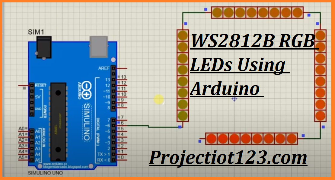
So, the current requirement of one pixel is almost 60mA. Arduino: DC Motors Diagrams & Code Brown County Library Warning: Make sure to plug the following components in correctly Transistors: Transistors have an. WorkingĮvery single WS2812B LED Pixels has three LEDs and also a control IC. The D IN pin of the LED Strip is attached to Digital Input and Output pin 6 of the Arduino. The 5v of Arduino and the LEDs are attached to an outer side power supply along with the GND. 50Hz PWM signal provides input to HIN and LIN pins.

Mosfets are used in half-bridge configuration mode. Single IC drives both high side and low side Mosfets.
#Power jack proteus library driver#
The above image shows connection between Arduino and the WS2812B RGB LED Strips. In this example, the half-bridge inverter circuit is designed using Mosfer driver and IRF530 Mosfets.


 0 kommentar(er)
